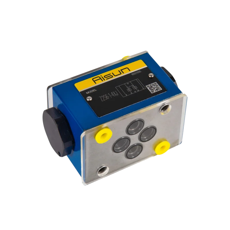
Directional valve 4WMM
The 4WMM directional valve is a type of hydraulic directional control valve, typically used in industrial and mobile applications for managing the flow of hydraulic fluid in a system.
Features of the 4WMM Directional Valve:
• 4-Way: The “4W” refers to the fact that the valve has four ports: one for inlet (pressure), one for outlet (return), and two for actuator connections (typically A and B ports).
Operation of the 4WMM Directional Valve:
The primary function of the 4WMM directional valve is to control the direction of flow of hydraulic fluid, directing it to different parts of the hydraulic circuit, which in turn controls the movement of actuators such as cylinders or motors.
Here’s how the valve operates in more detail:
1. Ports of the Valve:
• P (Pressure): This is the inlet port where the pressurized fluid from the hydraulic pump enters the valve.
• T (Tank/Return): This is the outlet port where the fluid returns to the reservoir or tank after performing work in the actuator.
• A and B (Actuator Ports): These are the two ports connected to the hydraulic actuator (such as a cylinder or motor). The flow of fluid through these ports determines the direction in which the actuator moves.
• Additional Ports: In some configurations, the valve may have additional ports for functions like pilot pressure or drain.
2. Valve Spool:
• The valve contains a spool (a cylindrical, sliding element) inside the valve body, which controls the flow paths between the ports.
• The spool can shift positions, and each position corresponds to a different flow configuration, controlling the direction of fluid flow through the system.
• The spool’s movement is typically controlled by an external force such as a solenoid (electrically operated), manual lever, or pneumatic actuator.
3. Valve Positions:
The 4WMM directional valve typically has multiple positions that determine how the hydraulic fluid is directed. Common configurations for the valve include 2-position, 3-position, or 4-position operation, which correspond to the number of distinct flow paths provided by the spool.
• 2-Position Operation: The valve is in one of two possible positions, either directing fluid to port A or port B.
• 3-Position Operation: In addition to the two basic flow directions (A or B), the valve also has a center position where both actuator ports (A and B) are blocked, and no fluid is allowed to flow to the actuator.
• 4-Position Operation: The valve has four distinct positions. This configuration can allow more complex routing of hydraulic fluid, such as switching between different actuator functions or allowing multiple actuators to work simultaneously with different flow conditions.
The spool movement can be shifted from one position to another by the control mechanism (e.g., solenoid, manual lever).
4. Flow Paths and Functionality:
• Position 1 (Flow to Port A): In the first position of the valve, the spool directs fluid from the P (Pressure) port to the A port, allowing fluid to flow into the actuator (e.g., a hydraulic cylinder), causing the actuator to move in one direction.
• Position 2 (Flow to Port B): In the second position, the spool directs fluid from the P (Pressure) port to the B port, causing the actuator to move in the opposite direction.
• Center Position(s):
o In the neutral (center) position, the valve may block fluid from both the A and B ports, effectively stopping the actuator. This position is typically used to hold the actuator in place.
o In other configurations, the valve may allow flow from one port to another or redirect fluid to the tank or return line when in the center position.
• Multiple Flow Paths: In 4-position configurations, the valve can provide more complex flow paths, such as allowing fluid to flow to both A and B ports simultaneously for dual-acting actuators or controlling different functions of the actuator.
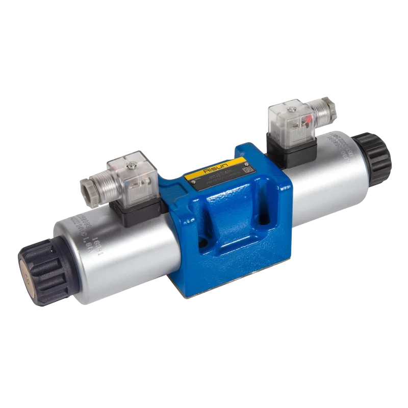
5. Actuation:
• The 4WMM valve is typically solenoid-operated, meaning it uses electrical signals to actuate the valve and shift the spool. However, it can also be actuated manually (by a lever or hand valve) or pneumatically (using compressed air) in some versions.
• Single Solenoid Actuation: A single solenoid can be used to shift the spool in one direction, while spring return can bring the spool back to its neutral position.
• Double Solenoid Actuation: In more advanced versions, the valve can have two solenoids, one for each direction of spool movement. This setup allows for more precise control and is common in automated systems.
6. Valve Performance Features:
• Flow Control: The 4WMM directional valve provides precise control over the direction and volume of fluid flow, which is critical for the smooth operation of hydraulic systems.
• Pressure Rating: The valve is designed to handle specific pressure levels, often rated up to 350 bar (5000 psi) or more, depending on the model and application.
• Flow Capacity: The valve is designed for high flow rates, capable of handling flow capacities typically ranging from 10 L/min to 400 L/min or higher, depending on the specific version of the valve.
• Leakage Prevention: The valve is designed to minimize leakage when in the closed or neutral position, ensuring efficient system performance and energy savings.
Types of Operation and Applications:
Common Valve Configurations:
• 2-Position Valve: In a basic 2-position setup, the valve can either direct fluid to port A (extend a cylinder) or port B (retract a cylinder). When in the neutral position, the valve blocks both ports.
• 3-Position Valve: In this configuration, the valve can stop the fluid flow to both A and B ports in the center position (e.g., hold position). The two end positions would direct fluid to either port A or B, depending on the desired actuator movement.
• 4-Position Valve: The valve offers four positions, which can be used to achieve more complex flow directions, such as simultaneous operation of multiple actuators or different flow rates for specific functions.
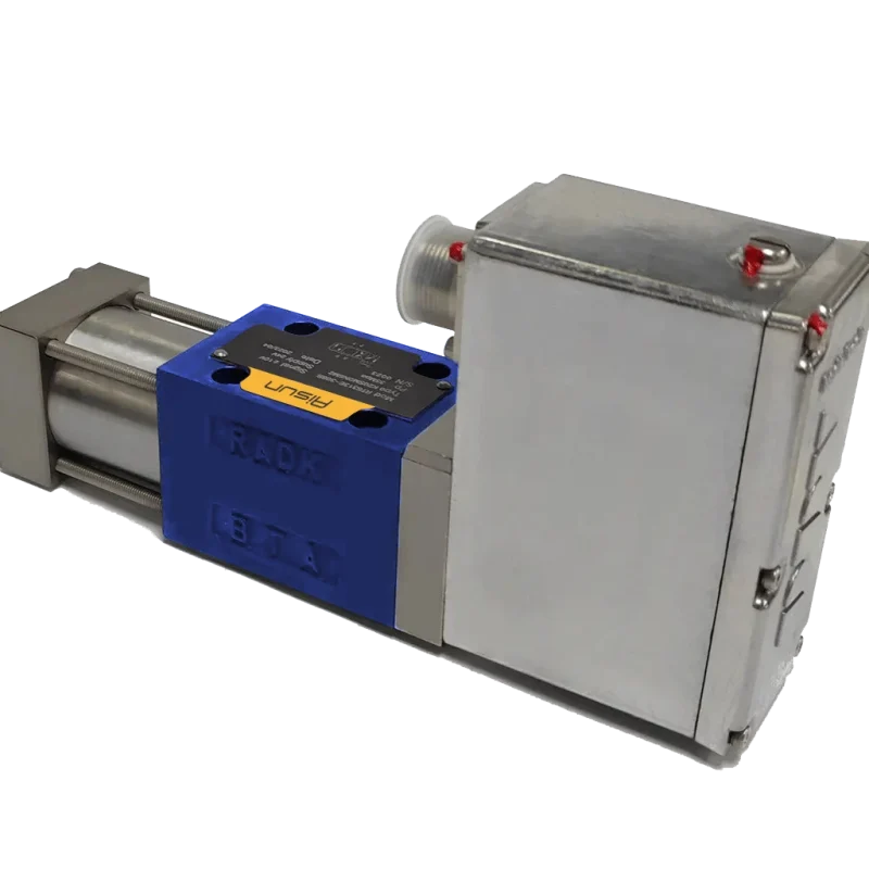
Applications:
• Industrial Machinery: Used in presses, machine tools, and automation systems for controlling hydraulic actuators and performing complex tasks.
• Mobile Equipment: Found in construction machinery (e.g., excavators, cranes, loaders), where fluid control to hydraulic cylinders is required for various movements.
• Hydraulic Systems: Used in hydraulic power units, lifts, and other systems that require directional flow control.
• Agricultural Equipment: Utilized in equipment like tractors and harvesters to control hydraulic implements and attachments.
• Test Systems: Used in hydraulic test rigs for precise control of fluid flow to hydraulic actuators during testing.
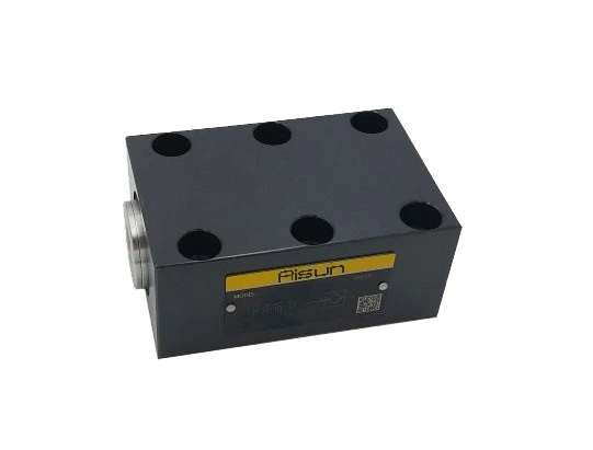
Directional spool valve WMM
Directional spool valve WMM
In the dynamic world of hydraulic systems, precise control over fluid flow is paramount. The WMM manual valve, specifically the manual directional valve, emerges as a crucial component that allows operators to seamlessly switch oil circuits through manual manipulation. This article aims to delve into the design intricacies, operational mechanisms, and diverse applications of the WMM series, shedding light on its pivotal role in hydraulic engineering.
WMM Manual Valve Overview: The WMM manual valve is a direct-operated directional spool valve designed to facilitate the switching of oil circuits by manually rotating the handle to axially move the spool. This versatile valve comes in 3/2-way, 4/2-way, and 4/3-way configurations, featuring various spool symbols.
The WMM series manual valve is renowned for its robust construction and reliable performance. Its design ensures efficient control over the flow of hydraulic fluids, making it an indispensable component in a wide range of applications. The valve body is made of high-quality materials, such as cast iron or aluminum alloy, which provide excellent durability and resistance to wear and tear. This ensures that the valve can withstand harsh operating conditions and maintain its functionality over a prolonged period.
Related products
Price range: $66 through $229
Price range: $71 through $124
Price range: $48 through $79
Price range: $2.761 through $3.312